Welcome to the RIBU1C Installation Manual! This guide provides comprehensive instructions for installing and configuring the RIBU1C SPDT pilot duty relay. Designed to save time and reduce costs‚ the RIBU1C offers a streamlined solution for controlling various loads. Follow the step-by-step instructions‚ technical specifications‚ and safety precautions to ensure optimal performance and compliance with electrical standards. This manual is perfect for professionals and DIYers alike‚ covering everything from pre-installation requirements to troubleshooting.
1.1 Overview of the RIBU1C Relay
The RIBU1C is a SPDT (Single Pole Double Throw) pilot duty relay enclosed in a durable housing‚ designed to simplify installations. It eliminates the need for separate components‚ saving time and costs. With a 10 Amp rating and a 10-30 Vac/dc or 120 Vac coil‚ it offers reliable control for various loads. The LED indicator provides visual confirmation of relay activation‚ while the compact design ensures easy mounting. This relay is ideal for HVAC systems‚ fan coils‚ and other applications requiring precise control‚ making it a versatile and efficient solution for installers.
1.2 Importance of Proper Installation

Proper installation of the RIBU1C relay is crucial for ensuring safe and reliable operation. Incorrect wiring or mounting can lead to malfunctions‚ electrical hazards‚ or reduced lifespan. Adhering to the manual’s guidelines ensures optimal performance‚ prevents overheating‚ and maintains compliance with safety standards. Proper installation also guarantees the relay’s efficiency in controlling loads and integrating with systems like HVAC or fan coils. Always follow the specified steps to avoid potential risks and ensure the relay functions as intended.

Key Features of the RIBU1C Relay
The RIBU1C is a SPDT pilot duty relay with an enclosed housing‚ designed to save installation time and costs. It offers efficient load control and durability.
2.1 SPDT Pilot Duty Relay Functionality
The RIBU1C operates as a Single Pole Double Throw (SPDT) relay‚ enabling efficient control of electrical circuits. Its pilot duty design ensures reliable switching for low-power signals‚ while the relay itself can handle higher currents. The SPDT configuration allows the relay to switch between two different circuits‚ making it versatile for various applications. With a 10 Amp capacity and a coil voltage range of 10-30 Vac/dc or 120 Vac‚ it offers flexibility and durability. The relay also features an LED indicator for visual confirmation of activation and is designed for up to 10 million mechanical cycles‚ ensuring long-term reliability. This functionality makes it ideal for controlling HVAC systems‚ fan coils‚ and other similar loads efficiently and safely.
2.2 Enclosed Housing Benefits
The RIBU1C’s enclosed housing provides enhanced protection against environmental factors‚ ensuring reliable performance in various conditions. This durable design eliminates the need for additional components‚ saving installation time and costs. The compact‚ all-in-one structure simplifies wiring and reduces space requirements. It also offers protection from dust‚ moisture‚ and other contaminants‚ making it suitable for industrial and outdoor applications. The enclosed housing ensures compliance with safety standards while maintaining ease of use and long-term durability. This feature is a key advantage of the RIBU1C relay.
2.3 Technical Specifications
The RIBU1C is a SPDT pilot duty relay with a 10 Amp capacity‚ suitable for controlling various electrical loads. It features a 10-30 VAC/DC or 120 VAC coil‚ ensuring versatility in different systems. The relay offers a high cycle life of 10 million mechanical cycles‚ providing long-term reliability. Operating temperatures range from -30°F to 140°F‚ and it supports non-condensing humidity levels. The compact design measures 1.70 x 2.80 x 1.50 inches‚ with a 0.50 NPT nipple for easy installation. An LED indicator ensures clear status monitoring‚ enhancing troubleshooting efficiency.

Pre-Installation Requirements
Ensure you have all necessary tools and materials‚ such as screwdrivers‚ pliers‚ and wire nuts. Verify the circuit is de-energized before starting the installation process.
3.1 Tools and Materials Needed
To ensure a smooth installation‚ gather the necessary tools and materials. You will need a screwdriver‚ pliers‚ and wire nuts for secure connections. Additionally‚ ensure you have the correct wires (10-30 Vac/dc or 120 Vac coil) and any required mounting hardware. For NEMA 4X housing installations‚ prepare conduit knockouts and locknuts. Always use compatible components to avoid damage. Ensure all materials meet local electrical codes and safety standards. Proper preparation will simplify the process and prevent delays.

- Screwdriver
- Pliers
- Wire nuts
- Mounting hardware
- Conduit knockouts (for NEMA 4X housing)
- Locknuts
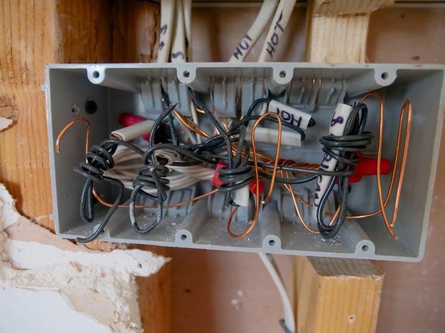
3.2 Understanding the Wiring Diagram
The wiring diagram is essential for correct RIBU1C installation. Identify the SPDT terminals: common (C)‚ normally open (NO)‚ and normally closed (NC). Wire colors indicate functions‚ such as white for 120 Vac. Connect the coil to the appropriate voltage source (10-30 Vac/dc or 120 Vac). Use the diagram to link the relay to controllers or thermostats. Ensure proper polarity and connections to avoid malfunctions. Refer to the diagram for specific load connections and verify all wires match their designated terminals. This ensures safe and efficient operation.
- Identify SPDT terminals (C‚ NO‚ NC)
- Connect coil to correct voltage source
- Follow wire color codes
- Verify polarity and connections

Step-by-Step Installation Process
Mount the RIBU1C relay securely‚ connect wires according to the diagram‚ and ensure all connections are tight. Follow the sequence to avoid errors and ensure safety.
- Mount the relay
- Connect wires properly
- Secure all connections
4.1 Mounting the Relay
Mount the RIBU1C relay in a suitable location‚ ensuring it is level and secure. Remove the conduit knockout from the equipment‚ insert the wires and nipple through the hole‚ and tighten the locknut. Ensure the relay is properly seated to prevent vibration. Follow the manufacturer’s guidelines for installation in NEMA 4X housing if required. Proper mounting ensures reliable performance and longevity of the relay.
- Remove conduit knockout
- Insert wires and nipple
- Tighten locknut securely
4.2 Connecting the Wires
Connect the wires carefully to ensure proper functionality. Identify the terminals on the RIBU1C relay‚ ensuring the coil and load wires are correctly paired. Use the white and black wires for the 120 Vac supply‚ connecting them to the controller or thermostat. Secure the wires firmly using wire nuts or connectors to prevent loose connections. Double-check all wiring before powering up the system to avoid electrical hazards.
- Identify terminals for coil and load
- Connect white/black wires to 120 Vac supply
- Secure wires with connectors or nuts
4.3 Securing the Connections
After connecting the wires‚ ensure all terminals are securely tightened to prevent loose connections. Use the provided locknut and nipple to seal the conduit entry point. Tuck wires neatly to avoid damage from moving parts. Apply electrical tape or heat shrink tubing for added protection. Double-check all connections for tightness before powering up the system. Properly securing the connections ensures reliable performance and prevents potential electrical hazards or malfunctions over time.
- Tighten terminals firmly
- Seal conduit entry with locknut
- Protect wires with tape or tubing

Wiring and Electrical Connections
Proper wiring is crucial for safe and efficient operation. Always follow the wiring diagram and ensure connections match the controller or thermostat specifications. Adhere to electrical safety standards.
- Understand wire color functions
- Connect to controllers or thermostats correctly
- Ensure all connections are secure
5.1 Understanding Wire Colors and Their Functions
Understanding wire colors is essential for correct connections. The RIBU1C typically uses standard color-coded wires‚ such as white/black for 120 Vac. Refer to the wiring diagram for specific functions. Proper identification ensures safe and efficient operation. Misconnecting wires can lead to malfunctions or electrical hazards. Always verify wire roles before connecting to controllers or thermostats. This step ensures compatibility and prevents potential damage to the relay or connected devices.
- White/Black: Common or 120 Vac input
- Other colors may indicate control signals
- Always consult the wiring diagram
5.2 Connecting to Controllers or Thermostats

Connecting the RIBU1C to controllers or thermostats allows seamless control of various loads. Refer to the wiring diagram for terminal assignments and follow manufacturer instructions. Identify the correct terminals for input and output connections. Securely attach wires to ensure reliable operation. Double-check connections to avoid errors. Use a voltage tester to confirm live wires before making connections. Power up the system and test functionality to ensure proper operation. This step ensures the relay functions as intended‚ controlling loads efficiently and safely.
Common Applications for RIBU1C
The RIBU1C relay is widely used in HVAC systems‚ fan coil units‚ and load control applications. Its versatility makes it ideal for integrating with controllers and thermostats efficiently.
6.1 HVAC Systems Integration
The RIBU1C relay is a perfect fit for HVAC systems‚ enabling seamless control of heating‚ cooling‚ and ventilation components. By integrating with thermostats and controllers‚ it allows precise regulation of system operations. Its SPDT functionality ensures that HVAC loads are managed efficiently‚ improving overall system performance and energy efficiency. This makes the RIBU1C a reliable solution for modern HVAC installations‚ providing robust control and durability in demanding environments.
6.2 Use in Fan Coil Units
The RIBU1C relay is ideal for Fan Coil Units‚ simplifying the control of fan and coil operations. Its SPDT functionality ensures precise load management‚ enhancing system efficiency. The enclosed housing protects internal components‚ reducing installation complexity. By integrating with thermostats and controllers‚ it provides reliable operation in HVAC systems. This makes the RIBU1C a key component for efficient and safe fan coil unit installations‚ ensuring optimal performance and energy savings.

Troubleshooting and Maintenance
Identify common issues like loose connections or faulty coils. Regularly inspect and clean contacts to ensure reliable operation. Perform routine checks to prevent wear and tear.
7.1 Identifying Common Issues
Common issues with the RIBU1C relay may include faulty connections‚ coil failure‚ or improper wiring. Check for loose terminals‚ corrosion‚ or overheating. Ensure the relay is rated for the load. Verify wire colors match the wiring diagram. If the relay fails to activate‚ inspect the coil voltage and ensure it matches specifications. Environmental factors‚ such as extreme temperatures or humidity‚ can also affect performance. Use a multimeter to test continuity and voltage drop across connections for accurate diagnosis.
7.2 Maintenance Tips for Optimal Performance
Regular maintenance is crucial for the RIBU1C relay’s longevity and reliability. Inspect terminals for corrosion and tighten connections periodically. Clean the relay housing to prevent dust buildup. Ensure the operating environment stays within specified temperature and humidity ranges. Avoid exposure to direct moisture or extreme vibrations. Use a multimeter to verify coil resistance and voltage. Replace the relay if any component shows signs of wear or failure. Schedule routine checks to prevent unexpected downtime and ensure consistent performance.
Safety Considerations
Ensure electrical safety by disconnecting power before installation. Avoid exposure to moisture and extreme temperatures. Follow proper grounding procedures to prevent electrical hazards and ensure reliable operation.
8.1 Electrical Safety Precautions
Always disconnect power before starting installation to avoid electrical shocks. Ensure the system is grounded properly to prevent hazards. Use appropriate wire sizes and avoid overloading circuits. Keep the relay away from moisture and extreme temperatures. Follow all local electrical codes and regulations. Wear protective gear‚ including gloves and safety glasses‚ when handling electrical components. Never bypass safety features or ignore warning labels. Ensure all connections are secure to prevent arcing or short circuits.
8.2 Environmental Operating Conditions
Ensure the RIBU1C operates within specified environmental conditions for optimal performance. The relay is designed for temperatures between -30°F and 140°F (-34°C to 60°C). Humidity should not exceed 95% non-condensing. Avoid exposure to direct sunlight‚ water‚ or corrosive chemicals. The enclosed housing (e.g.‚ NEMA 4X) protects against dust and water jets but is not submersible. Proper ventilation is essential to prevent overheating. Mount the relay in a stable‚ vibration-free area to ensure reliable operation and longevity of the device.
Successfully installing the RIBU1C ensures optimal performance and reliability. Follow the manual’s steps for a seamless setup and enjoy efficient load control in your applications.
9.1 Summary of Key Installation Steps
Mount the RIBU1C relay securely‚ ensuring proper alignment. Connect wires according to the diagram‚ matching colors to their functions. Tighten all connections firmly to prevent loose contacts. Verify the correct power supply and load connections. Double-check the wiring for accuracy before powering up. Ensure all safety precautions are followed‚ such as turning off the power supply during installation. Test the relay’s functionality to confirm proper operation. Refer to the troubleshooting section if any issues arise. Proper installation ensures reliable performance and longevity of the relay.
9.2 Final Checks for Proper Functionality
After installation‚ verify the LED indicator lights up when the relay is activated. Ensure the relay produces a clear “click” sound when energized. Test the load operation to confirm it turns on and off as intended. Check for any unusual noises or odors‚ which may indicate improper connections. Verify all wires are securely fastened and not loose. Ensure the relay controls the load accurately according to the controller or thermostat signals. If any issues arise‚ consult the troubleshooting section for guidance. Proper functionality ensures safe and efficient operation.